TOFE - Tim’s Open FPGA Expansion
The TOFE interface dramatically reduces the cost of high-speed I/O functionality by taking inspiration from the PCI-Express standard and re-purposing its connectors and mechanical specifications.
TimVideos and Numato are committed to developing expansion boards to add new features (such as VGA capture) to the Opsis board through the TOFE connector. We also plan to create simple adapter boards to other existing expansion I/O standards such as PMOD and the Digilent VHDCI.
We hope that the significantly reduced cost of the TOFE interface will also enable the community to create new expansion boards we haven’t even dreamt of yet!
Why?
We want a FPGA expansion that fits the following criteria;
- Open standard that anyone can access without NDA or other agreements.
- Cheap connection interface that are easily accessible to any hobbyists.
- Supports high speed signals >5 Gbit/s.

Document examining wide variety expansion board interfaces
Specification
Naming
Motherboard Connectors
The aim with naming of a TOFE motherboard connector completely describes the features available.
The name scheme needs to include;
- PCI Express connector size
- 1x
- 4x
- 8x
- 16x
-
The number of lanes populated. To improve brevity, if the number of lanes populated is left out then all lanes in the connector should be populated.
- If the connector supports “bi-directional” or “uni-directional” signaling.
- B - Bi-Directional
- S - Uni-directional
- The maximum operating lane speed;
- 1500M
- 3125M
- XXXXM
-
The minimum operating lane speed. If unspecified, then it is assume the lane can operate down to DC.
- The compatible IO standards that are supported.
- Voltage levels which are compatible.
- 1.5V, 1.8V, 2.5V, 3.3V.
- Signalling standards.
- LVDS - Low Voltage Differential Signaling
- RSDS - Reduced Swing Differential Signaling
- PPDS - Point-to-Point Differential Signaling
- TMDS - Transition Minimized Differential Signaling
- BLVDS - Bus LVDS
- Line encodings which are compatible.
- 8b/10b - Used by pretty much everything.
- 64b/66b - 10 Gbit/s Ethernet
- 64b/67b - Interlaken
- 128b/130b - PCI-Express Gen 3 and higher.
- 128b/132b - USB3.1
- Voltage levels which are compatible.
- The amount of power that can be provided,
- All together (from both 3.3V and 12V combined).
- Just via the 12V pins.
- Just via the 3.3V pins.
- Any extra properties that could be useful like;
- Beacon signaling for PCI Express compatibility.
- SATA Out-of-Band signaling.
Daughterboard
The aim with naming a TOFE daughter board is to completely describe the features required for the daughter board to correctly operate.
PCI-Express
PCI-Express cards are actually compatible with TOFE motherboard sockets which meet the following requirements;
| Version | Generation | Lane Speed | Line code |
| 1.0 | Gen 1 | 2.5 Gbit/s | 8b/10b |
| 2.0 | Gen 2 | 5.0 Gbit/s | 8b/10b |
| 3.0 | Gen 3 | 8.0 Gbit/s | 128b/130b |
| 4.0 | Gen 4 | 16.0 Gbit/s | 128b/130b |
PCI-Express 1st gen would be TOFE-Xx-3000M-PS
Spreadsheet of connections
Comparison
| TOFE | Digilent VHDCI | FMC LPC | FMC HPC | Altera HSMC | ||||
|---|---|---|---|---|---|---|---|---|
| Open Specification | Yes | None | No | No | Yes | |||
| Autodetect and Configuration Interface | SMBUS or JTAG [5] | None | JTAG or SMBUS | JTAG or SMBUS | JTAG or SMBUS | |||
| Power | 12V and 3.3V | 3.3V or 2.5V | 12V, 3.3V and adjustable | 12V, 3.3V and adjustable | 12V and 3.3V | |||
| Transceiver Pairs | Up to 14 RX and 14 TX | 0 | 0 | Up to 10 | Up to 8 RX and 8TX | |||
| LVDS Pairs | ||||||||
| Total | Up to 34 | 22 | Up to 34 | Up to 80 | Up to 18 TX and 18 RX | |||
| IO Pairs | Up to 34 [6] | 22 | ? | ? | Up to 16 TX and 16 RX | |||
| Clock Pairs | Up to 7 [6] | 2 | ? | ? | Up to 2 TX and 2 RX | |||
| Additional low speed IO | 11 | 0 | ? | ? | 4 x IO, 2 x CLK | |||
| Connector | ||||||||
| Motherboard | PCI-Express ~$1 USD |
VHDCI ~$8 USD |
Low Density FMC ~$30 USD |
High Density FMC ~$80 USD |
HSMC ~$5 USD |
|||
| Daughterboard | None ~$0 USD |
VHDCI ~$8 USD |
Low Density FMC ~$30 USD |
High Density FMC ~$80 USD |
HSMC ~$5 USD |
|||
Mechanical
TOFE boards should be mechanically identical to PCI-Express half length cards in either full height or half height (also called low profile).
However, the only regions which matter for TOFE boards are the PCI-Express fingers and the mechanical drill holes. See the following diagram;
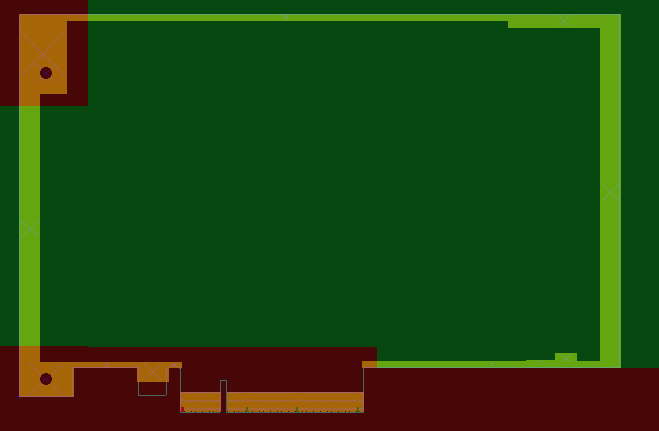
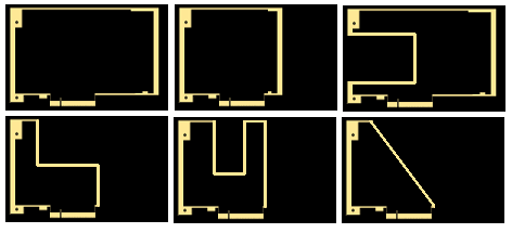
Any of the area marked in green is free to be changed. This offers a wide range of mechanical designs, such as shown in this diagram;
Boards
Existing
These boards are currently available;
Planned
These boards are planned for construction or currently under development;
Adapter Boards
Boards which adapt to other standards for peripheral interfacing.
-
To PMOD - Simple passive adapter which allows PMOD based peripherals be used on a TOFE header.
-
To VHDCI Adapter - Simple passive adapter which allows usage of peripherals designed for the Digilent Atlys board.
-
To Arduino Shield - Adapter which is compatible with Arduino shields. Contains an ADC/DAC to be compatible with the Analog pins.
-
To FMC LPC - Adapter which is allows FMC LPC compatible boards be used on TOFE expansion.
Functionality Boards
Boards which add new functionality to TOFE compatible device.
-
VGA Input - Adaption of Rohit’s vmodvga designed with a TOFE interface rather than a VHDCI interface.
-
4 x HDMI - Board which adds 4 x HDMI ports using a 8xTOFE connector.
-
3 x 1G Ethernet - Board which adds 3 (maybe 4?) x Gigabit Ethernet ports.
-
? x SDI - Board which adds SDI interfacing capabilities.
Templates
A KiCad template for TOFE boards can be found on GitHub.